This all started with a Website and a man's idea. Somender Singh came up with a method of altering the combustion chamber to provide a much quicker and cleaner burn. On his website there are a number of testimonials of people who have applied his principles and achieved fantastic results. With his principles one can run an engine at higher compression without detonation, get more power, lower emissions and a jump in fuel economy. So, since I can't leave well enough alone, I thought I'd jump in and give it a shot myself.
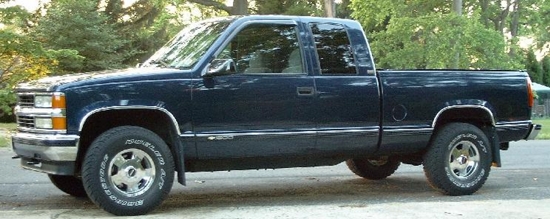
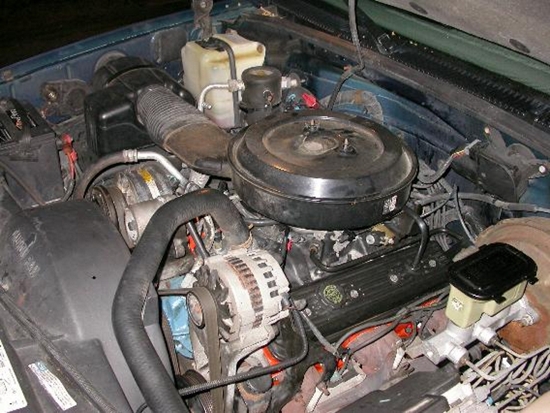
I decided to try this out on my daily driver. It is a 1995 Chevrolet K1500 4x4. I like this truck for a number of reasons. Its paid for, parts are cheap, its dependable, it looks good, its fairly comfortable to drive and it has ample capacity to drag anything around I may need. What I do not like is the mileage, averages around 13.5 mpg between city and highway. The best I have ever gotten has been 17.5 mpg on the highway on only 2 tank fulls in the 35,000 miles I have put on it since I owned it. So what better vehicle to try this on! Plus with 164,000 miles on it, those valve seals are probably leaking a bit anyway.
Note: Some of the following images you can click on. Click on these images to open larger image in new window or right click to download.
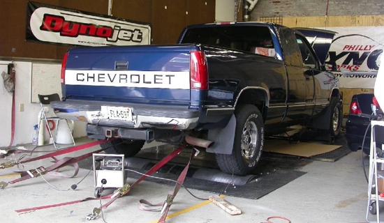
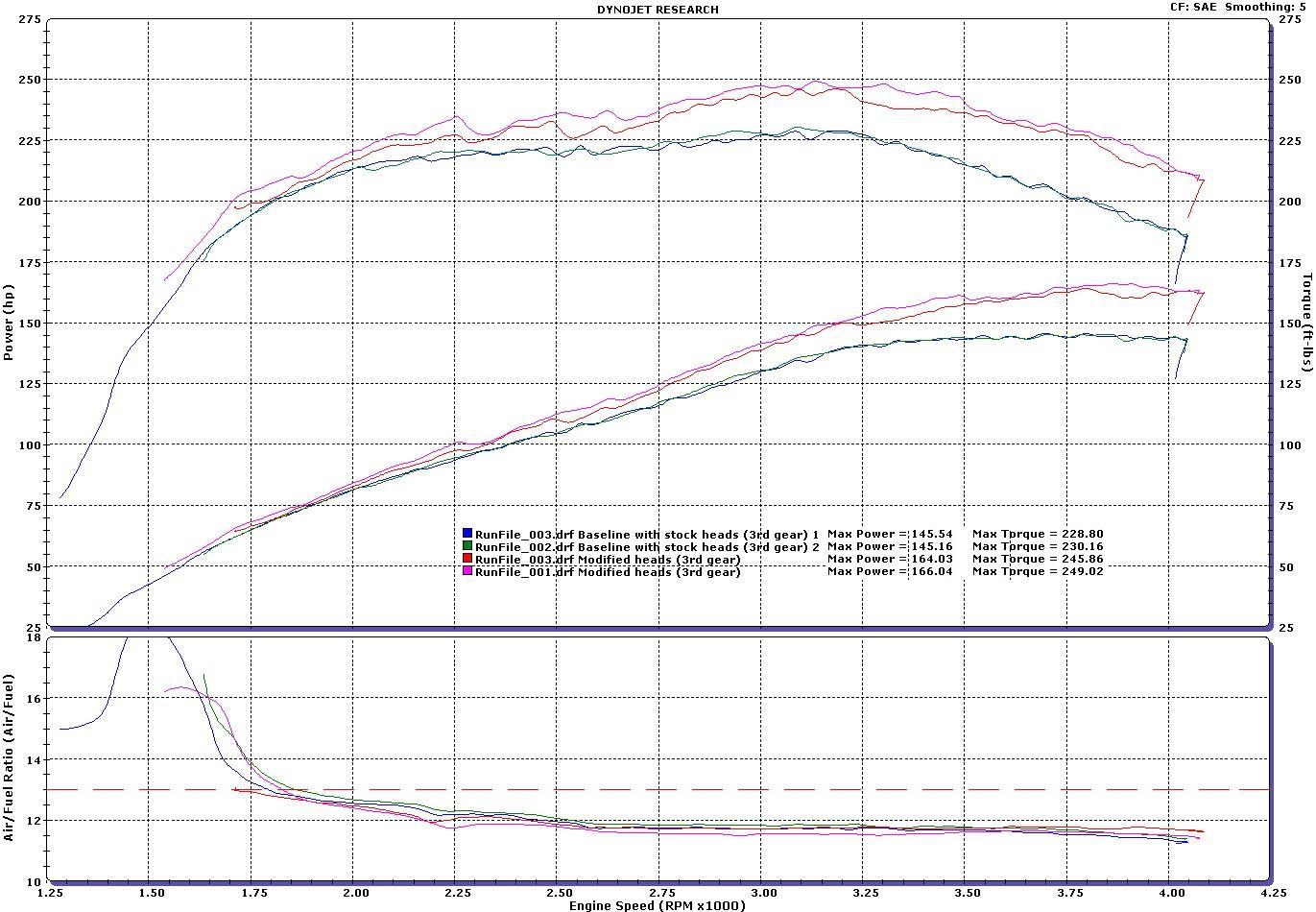
To start with I needed to see where I am at, that way I can detail what kind of improvements became from this head modification. I already know my mileage from logging it over the last 35,000 miles. Also why not compare the power and torque out put of the engine. To do that I went into Philly Dyno Works and ran it on their DynoJet inertia dyno. Below shows the graphical results of the before and after modification. There are 2 runs from before and 2 runs from after. The before is the stock engine just as it left the factory 11 years and 164,000 miles ago. The after runs are with the head modification detailed below. The truck has an automatic governor that cuts the engine out when you hit 100 mph, so in 3rd gear with the torque converter off, that was as far as I could take the graph. Redline is 5000 rpm for the engine, but 100 mph came a bit sooner.
Now to find a set of heads! I located a set of heads on Ebay that looked like they would work as they were similar to the casting number I thought I had on the engine. Later, I found out, these were in fact the same casting number as was on the truck (14102193) so that was even better! Now to figure out what I had and what I wanted to do.
Stock Engine Specs
1. Cylinder head volume 64 cc (casting #14102193)
2. Piston head volume 10 cc
3. Head Gasket thickness 0.040" (although the old ones measured 0.030" when I removed them)
1. Deck Heads 0.060" (with grooves gave me a 58.5 cc cylinder head volume)
2. Add grooves to each squish area on each side of plug
3. Use a 0.015" head gasket to get compression of 10.2:1
4. Groove backs of intake valves
5. Add grooves (Power Lynz) to intake tracks with Dremel
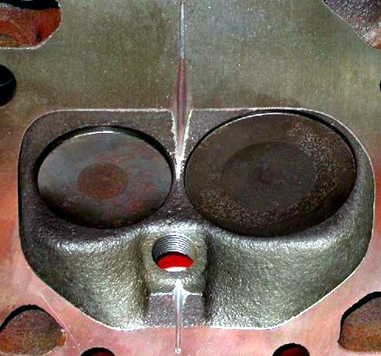
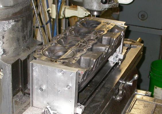
The next series of pictures show The actual modifications to the heads. I put in the base grooves first with a 1/16" ball nose end mill, then I had them decked. This decking created a smaller squish area on the back side of the plug. This was why I added the groove to this area. After the decking, I went back and cleaned up the grooves by hand with a file to get the exact shape I wanted.
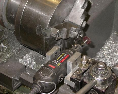
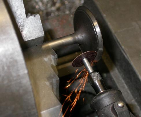
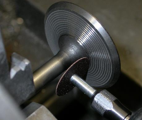
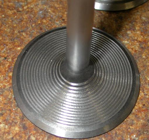
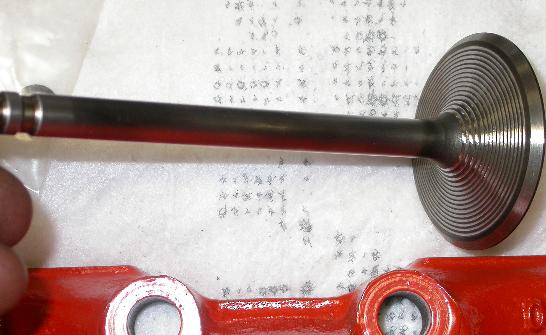
After the heads it was time to do the valves. Mpgmike on the MPG Research forum suggested grooving the backs of the intake valves. This would create just a bit of turbulence as well as hold some gas on the surface. All this helps with better atomization which, gives us better combustion. The handy dremel and a custom holder for it on the lathe helped accomplish this task.
Now back to the heads again. Mpgmike has been trying out something he calls Power Lynz, which are basically threading the intake port to again help add some turbulence and trap gas so that it has more time to vaporize and therefore we get better combustion. Also as the heads normally run quite warm, we have the added benefit of the heat itself acting upon gas in these threads. All I had was a dremel, so I made a makeshift stop and proceeded to cut some grooves in it as far as I could to try and mimic this as best as possible.
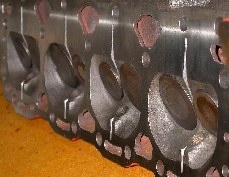
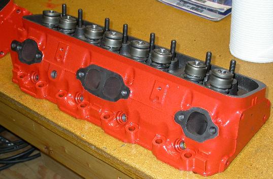
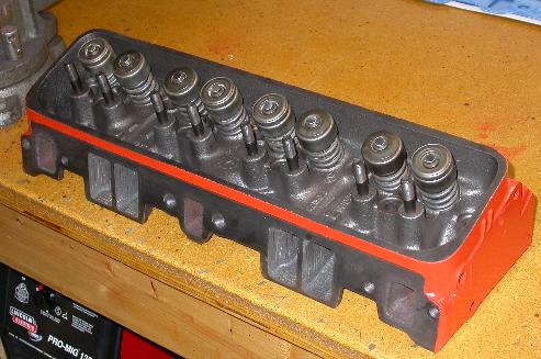
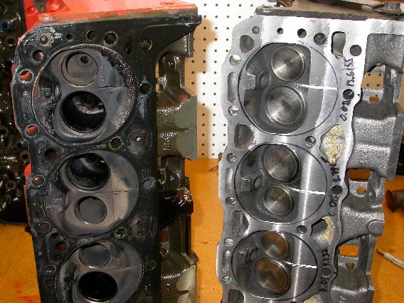
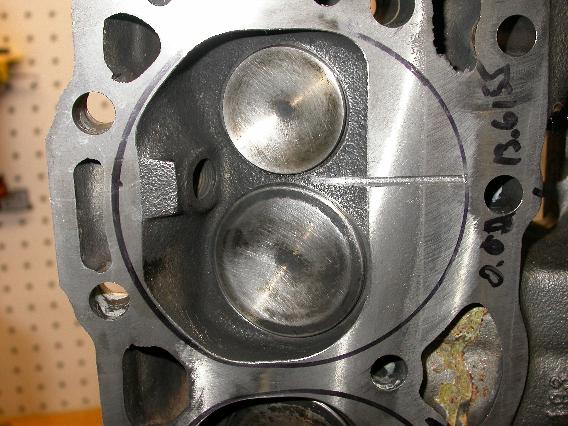
Here are the finished results of the heads, painted and ready to go. To check everything I did a mock up on an 1987 Chevy block I had. I found out I had to shave the intake to get it to fit. To simulate the head gaskets there are 2 layers of file folders squished in between the heads and block. You can see how the grooves look from the inside in the one picture.
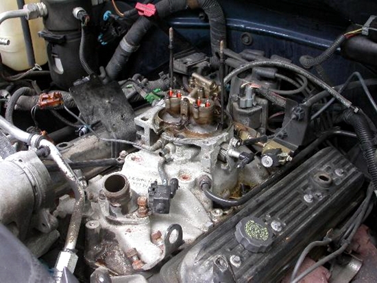
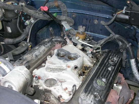
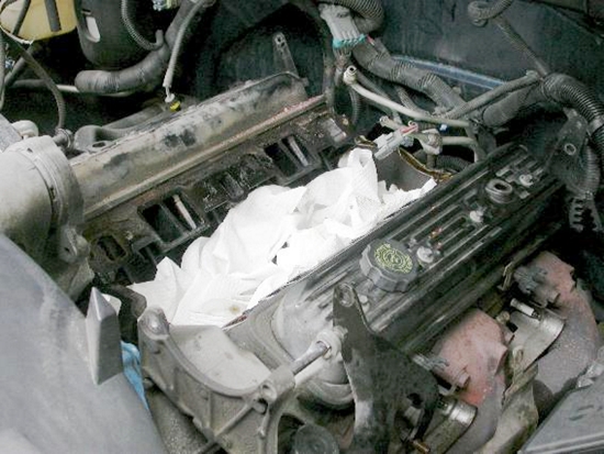
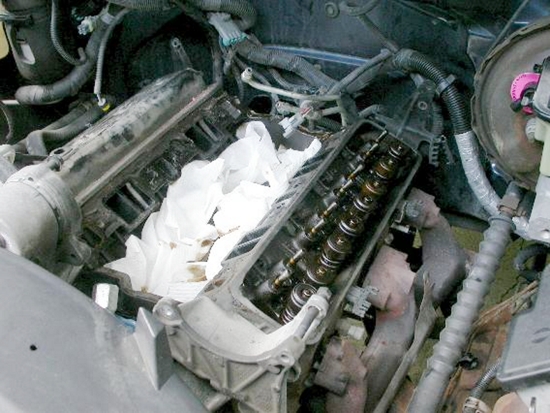
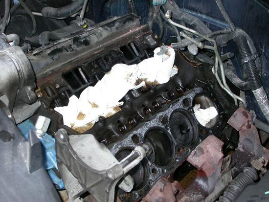
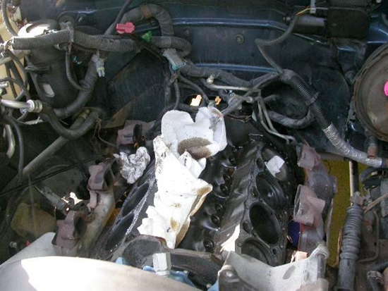
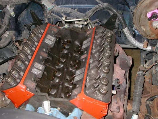
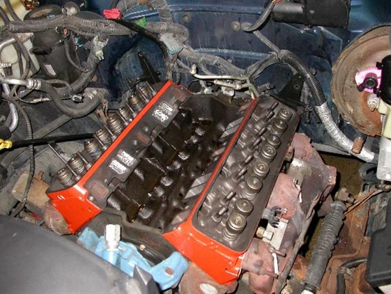
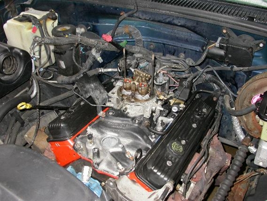
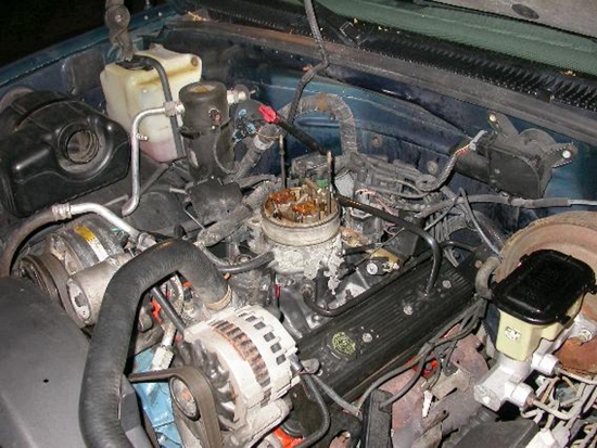
Now for the real work! Time to disassemble the engine down to the short block! The hardest part was getting the power steering pump out. The pulley was pressed on, and that had to be pulled off with a puller so I could get at the bolts to get the pump off the bracket. It had to come off the bracket because it blocked a single bolt that held the bracket to the head. What a pain! Other than that I took my time and made sure I did not do anything detrimental. Also a good shop vacuum works great for sucking all the crud that will inevitably fall into the cylinder bores when you pop the old heads off.
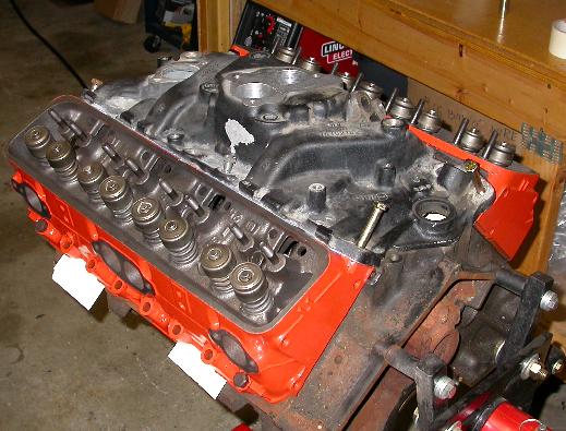
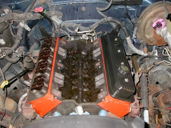
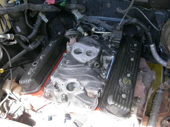
Here is putting it all back together! I gave up about 2 am Sunday morning and got some sleep. Started fresh at 9 am and worked through the day. Then at 8 pm, the most exciting moment! Time to fire it up and see if I put everything back together right or not! Did I put that distributor back in right? Were all those plug wires in the right spot? Did I adjust those rocker arms correctly? Would there be any unfortunate oil or coolant leaks? Yikes... I almost thought of just leaving it as it looked pretty good without starting it... but I didn't... Turned the key and it fired right up! VROOM! SUCCESS! (well, at least it ran again!)
Well that chronicles Part I of the groovy heads experiment. The valves seem to have seated and the idle is very smooth, down to 550 rpm in gear and it stays very smooth. The second dyno run confirms both the power and torque increased, although I did raise the compression so that would be expected. Initially there was a slight, but noticeable knock right off idle under light to moderate load. I could get it to do it by holding the brake in gear and revving it up to 1100 rpm in the driveway. Step on the gas more and it would go away as you rev past 1500 rpm. I ran about 1/3 cup of water through each bore on the throttle body to try and steam clean off the tops of the pistons and then just put some miles on it. After a week or so, it seems to have disappeared. Either there was excess buildup (from the last 164,000 miles) on the pistons that were getting in the way of the squish area, or the ECU has learned to shift the timing as to control the knock at these points. Either way, it looks like we are in the clear and time to see road mileage and performance.
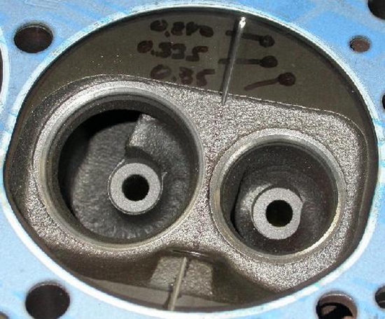
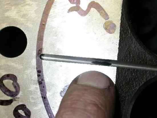
Failure?! Ok, not CATASTROPHIC failure, but no matter what I did, I could not lean out the engine and not feel it, or see any mpg gain. And as I put on the miles, it seemed to run worse. The idle got rougher and as I approached about 3500 miles, the detonation knock started getting worse! Ok time to think!! If one researches other grooves and compares them to mine, what does one see? Others are either wider or deeper and angle into the squish area. Look above, my first grooves are 0.063" wide, 0.040" deep and are parallel to the deck surface through the squish area. The blending I did into the combustion chamber only really angles them after they are into the dished area of the piston. So as I thought about it I could see how any real direction of turbulence into the groove could be getting chocked as it tried to go into the little tiny groove and more than likely was bouncing off and not "grooving" at all. So, I decided to take another crack at it!
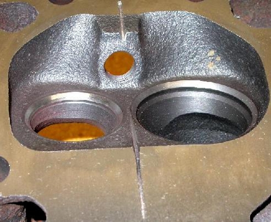
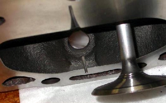
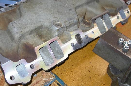
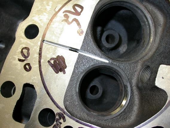
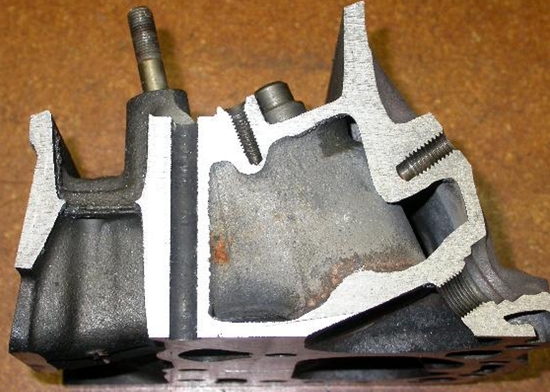
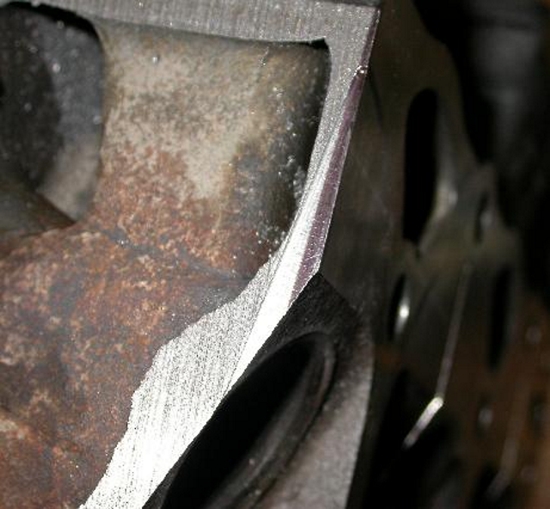
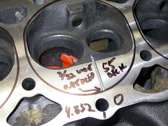
I bought a 3 inch shell mill so I could do the decking myself. With some careful fixture making and taking time to level the head to the mill it was quite easy. I tried to be daring again and do a 0.070" deck with a deep groove. I found out what its feels like to groove right into the water jacket (luckily I actually grooved deep enough to break through instead of being paper thin and discovering it after they were on the engine). Luckily, I was able to find a set of heads on Ebay that were virtually new (valve job already done), for under $200. Since I had a now destroyed head, I was able to slice it up and see exactly how much room I had to work with. See the black mark which is how deep I planned to groove the new heads, giving me about 0.100" of thickness on the deepest part. That should be enough for a stock motor to run.
Note: Some of the following images you can click on. Click on these images to open larger image in new window or right click to download.
Ok, after thinking this over a bit I decided to be a bit more conservative. With dished pistons 10:1 is about all I can hope for. Lets not destroy anymore heads and let's keep Mr. Singh's recommendations in mind on squish clearance. Let's just get the idea WORKING!
2nd Head Modification Objectives
1. Deck Heads 0.055"
2. Add 1 groove large squish area opposite plug.
3. Use a 0.033" head gasket to get compression of 10.0:1 (0.063 squish clearance).
4. Leave intake valves alone.
5. Leave intake tracks alone.
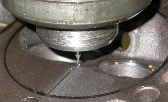
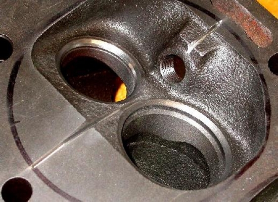
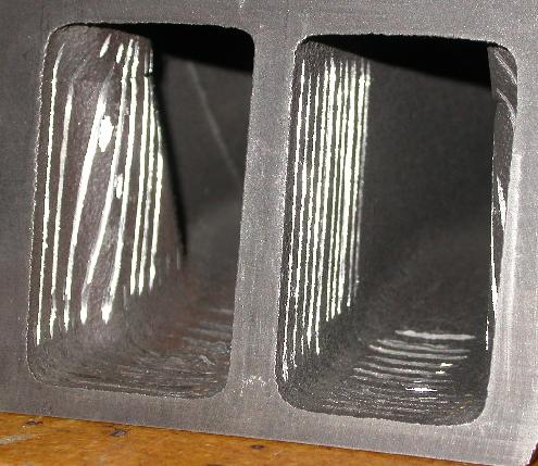
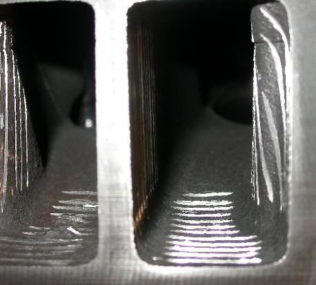
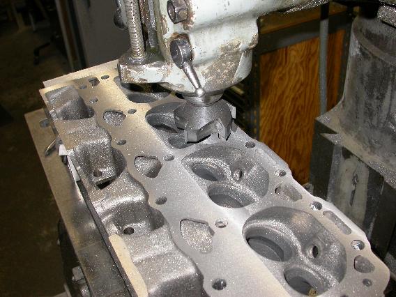
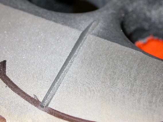
Here are some pictures of the milling and grooving process. These grooves are 3/32" wide and 0.040" deep at the outer ring area and taper at about 4.5 degrees as the go into the combustion chamber. At the deepest part they are about 0.125" deep. I then did a light cleanup (took off rough edges) and blending into the combustion chamber. This kept the max amount of material so I didn't loose precious compression, while keeping sharp edges from developing hot spots.
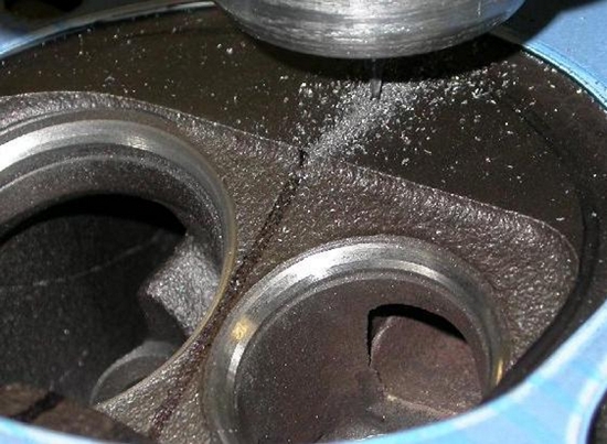
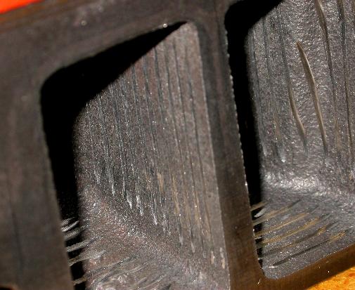
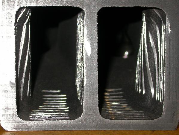
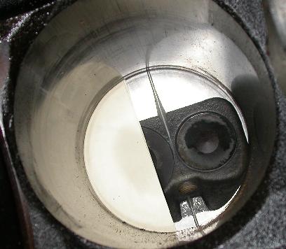
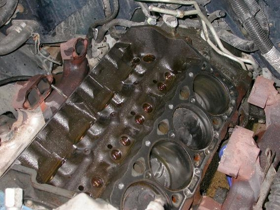
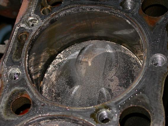
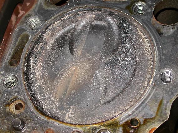
Upon taking the old heads off I found a ton of crud on both the pistons and heads. You can see how the burn pattern is not going up the groove but indeed seems to be bouncing off where it narrows. The tight squish clearance and trying to run it lean sure didn't help keep it free from deposits. I imagine there is some oil being burnt on an engine with this many miles. I cleaned the pistons and area on the bore above the rings very carefully and cleanly before I reassembled it. All that sure wasn't going to clean itself off, so with a razor blade, shop vacuum and air gun in hand, it was cleaned till it was good as new. The last picture you can see the new groove on the assembled head. Also the grooves on the intake valves did nothing more than to catch crud and gunk as they were covered in black goo on the backsides. Being a wet manifold, every time the engine is shut off, there is a whole lot of gasoline that is in the manifold and runs down and literally bakes on it and the valves. I was very surprised at the amount of accumulation after only 3500 miles. I should probably run injector cleaner through this thing regularly, especially since I make only a short trip to work every day.
I got to thinking about why this was so dirty after such a short time. Remember I used an ultra thin 15 thousands gaskets? I never did anything with the block, so I was relying on a 12 year old block with 164k miles to be flat enough to seal with this ultra thin head gasket. Probably not the wisest idea, and I bet much of this accumulation was just oil leaking past the head gaskets as it was probably impossible for that block to be flat enough to seal correctly. Of course and excess oil in the cylinder would also find its way into the intake track and bake on with the liquid gas creating the mess you can see.
I had a few problems after reassembly (which ended up being a dumb mistake on my part), and I ended up chasing a bad miss that would show up as you got to 50% or more throttle at 70 mph or above. After replacing every part of the ignition system from the distributor to the plugs, I finally replaced the spark plugs. The miss disappeared! Here a bad spark plug (and yes I did have all 8 old ones on the bench to glare at with a nasty look, wondering just which one it was) was the cause of the miss. Once replaced, the miss was gone and things were running good. As I was still chasing the miss, I retarded the timing about 5 degrees and was able to 18+ mpg cruising at 75 mph on one tank in spite of the miss. That's a new high.
Everything seemed to run very well for a few months. I was busy and did not have time to mess with it much. All of a sudden over the course of a week, it developed a terrible detonation problem. Nothing was changed under the hood to bring this one, it was just all of a sudden. It was so bad, it almost sounded like a diesel at times. the only way to cure it was to advance the timing quite a bit, past even the stock setting. This cured the knock, but certainly dropped off the extra torqueiness and quick throttle response the engine had with the retarded timing.
What could have caused this? Unfortunately, I just haven't had the time to mess with it since then. I suspect that again I need to rethink my grooves. I think I needed to V shape them more. The milled depth and width were ok, but they do not V out. I wonder if maybe they partially clogged up? This could have caused this sudden detonation problem, as we are still at 10:1 compression instead of the stock 9:1. The engine still runs super smooth and does have decent power, but with the timing where it needs to be to keep it from knocking, its not nearly as responsive as it could be. Average mileage seems to be about the same as before. It would be interesting to pop these heads back off and see what they look like, then file them into more of a Vee. I think this would really do the trick. Currently though I just have not had the time to devote to that as it is a 2 or 3 day project to pull everything apart.
So do the grooves help? After doing this project I was contacted by Mr. Singh about the possibility of testing for more tangible results. I ended up building a special test dyno and running a series of detailed tests. Things were kept simple, just a test of an engine stock, and then one with grooves added. Results showed small but significant differences, as the engine only had small grooves and nothing like increased compression was done. Please see the reports on the Singh Groove Tests Page.